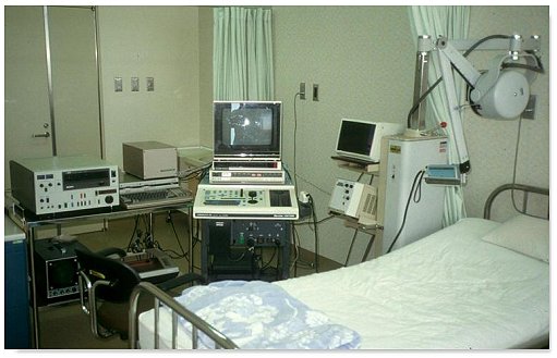
Dr. K Baba's setup for 3D ultrasound in the mid 1980s. A linear array probe was mounted on an articulated arm of a static scanner for position sensing. In the middle is the real-time scanner and on the left the video-recorder, an essential part of the setup.

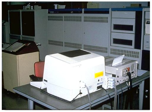
Dr. Baba's computer setup for making the calculations.
" ...... The data from the position-sensor attached to an ultrasonic probe are entered into a microcomputer, where they are converted into a form that can be recorded on a video tape as an image. This new image is simultaneously superimposed on the ultrasonic tomographic image and recorded on the video tape. Thereafter, these new data on the video tape are entered into the minicomputer. This minicomputer produces three dimensional reconstructions, and using computer-graphics displays the images which were generated on television monitor.
Separation of data acquision from data entry was done in order to make the examination time for patients as short as possible, so that discomfort to the patients was reduced and the effect of fetal movement was minimised.......".
For 3-D Reconstruction and display: " ...... A minicomputer VAX11/780 (DEC) system was used for both the 3-D reconstruction and 3-D display. A repeating video tape through column feeding in the computer room, necessary images were input to this minicomputer on the basis of positional information of the probe displayed on the monitor TV. The image of the anterior uterine wall was excluded to define that of the fetus more clearly. Simultaneously, the data were compressed in the format of 128 by128 picture elements which were then piled up in the memory of the minicomputer as 3-D data. The threshold level of brightness was designated in such a way that the fetus could be separated from the amniotic fluid. Thereafter, the 3-D images are displayed on a monitor TV using computer-graphics.... ".
Although it took a few second to 'acquire' the slices of image with the probe moving over the maternal abdomen, it took approxmately another 12 minutes for further processing, 10 minutes for the data input and 2 minutes for the 3-D reconstruction and display. Hence the 3-D image cannot be generated in real-time or near real-time.
Images courtesy of Dr. K Baba. Reproduced with permission. Description of the early setup excerpted from "Development of an ultrasonic system for three-dimensional reconstruction of the fetus" by Kazunori Baba et al. J Perinat. Med. 17 :19, 1989.
Back to History of Ultrasound in Obstetrics and Gynecology.